welcomeDawopu Group
Language selection:
 ∷
∷

∷
 ∷
∷
Abstract. In this work the method of computer modeling solved the problem of reducing the efficiency of the turbocharger associated with the mismatch of the geometry of the resulting casting petal turbine technology geometry, calculated gas-dynamic calculations. Computer methods was calculated crystallization of the casting and hardening of the stencil. Computer simulation showed that there is a significant change in the geometry of the turbine blade, which adversely af- fected the geometry of the resulting casting. Was proposed and solved by the method of computer simulation of "reverse" task of the task of such a geometry of the mold, the solidification of the stencil in water and its deformation led to a (given) geometry of the resulting casting of the turbine of the turbocharger. The solution of this problem by the method of computer modeling allowed to reduce the production defect on the discrepancy of the turbine blade geometry of the turbocharger by 90 %.
Keywords: computer-integrated design, optimization, turbocharger, turbine wheel, engine
It is widely used turbochargers to force the internal combustion engine by supercharg- ing, to utilize the residual energy of the gases of the exhaust in the cylinders of inter- nal combustion engines. A large number of publications are devoted to the problems of design of turbocharger wheel structures and their optimization by gas-dynamic, strength and dynamic criteria [1-10]. Designs of the Ukrainian turbochargers of the TV series (TKR-7.5 TV, TKR-8.5 TV and their modifications) for diesels of agricul- tural and transport cars on the design characteristics don't concede to the best foreign
analogs. In accordance with the criterion of performance characteristics of cast parts of the engine (details determining the performance of power, fuel consumption, effi- ciency, etc.) in computer-integrated resource design is necessary to conduct the fol- lowing studies:
· Investigation of the influence of the geometry of cast parts of the internal combus- tion engine on their performance;
· Identification of possible deviations of the geometry of the cast parts on the stages
of the technological process of their production;
· Simulation of phase transitions in the manufacture of cast parts;
· Investigation of VAT and its influence on the geometry of cast parts.
However, the quality of the real turbochargers in addition to the design stage is largely determined by the quality of the manufacturing stage, which is due to the presence of a certain level of technology and quality management (control) system. At the same time, experienced and commercially produced samples can actually have different quality indicators. Among the production operations that determine the con- sumer level of the turbocharger as a product, are the achievement of the required roughness of gas and air channels, exact compliance with the design of the real di- mensions of the sliding bearing, gaps, passage sections of diffusers and snails, high- quality performance of friction welding operations of the turbocharger and shaft, rotor balancing and others. But, as in the design, are particularly significant technological errors in the manufacture of turbochargers’ impellers. Turbine and compressor impel- lers, which are the most functional and loaded elements of the turbocharger, actually determine the quality of the entire structure. The experience of control studies within the framework of the author's supervision of the quality of manufacture of turbo- chargers, in particular casting of impellers of JSC "AVTRAMAT" (Kharkiv) and JSC "Kupyansk foundry" (Kupyansk Kharkiv region) show the presence of potential op- portunities to improve the quality of mass-produced products.
It is known that "quality" is a set of properties and characteristics of products or services that give them the ability to meet conditioned or anticipated needs. For a turbocharger, these are the efficiency of the working process (estimated efficiency of the turbocharger or a decrease in the specific effective fuel consumption of engines in the entire field of operating modes), and the level of reliability. Manufacturing errors, respectively, can both worsen the working (gas-dynamic) characteristics of the turbo- charger, and reduce the margin of safety, leading to an increase in the fuel consump- tion of the engine, the absence of the planned power level, the breakdown of the im- pellers. In connection with the absence of the results of studies in the literature on the sensitivity of the design of the impellers to technological errors in this article, an at- tempt is made to analyze the level of errors in the shaping of the impellers of turbines and to identify ways for their further study and minimization [10-12].
The technology of manufacturing of impellers, in the world of engineering relates to so-called "high technologies", which underlines their complexity and knowledge intensity. Turbine impellers are made by casting on melted models. With a relatively low cost and high productivity characteristic of this method, there are a number of technological problems that make it difficult to obtain impellers with the planned
geometry due to the inevitable errors that occur at different stages of production. Such stages, considering them coinciding with the number of reflections of the profile sur- faces, for the turbine wheel five [13-14].
Initially, when developing the technology of mass production of turbine wheels, the main attention was paid to the stability of the thickness field for blades having a complex spatial shape. However, in the transition from analog design methods (fol- lowed by experimental refinement) to computer-aided modeling and optimal design methods (for gas-dynamic and strength parameters), it was found that the deviations of the turbine wheel blade profile from the nominal, arising in the manufacturing process and difficult to control, significantly affect the main performance characteris- tics (efficiency of the turbine and turbocharger as a whole).
The aim of this work was to solve the problem of reducing the efficiency of the turbo- charger, associated with the discrepancy between the geometry of the resulting cast- ing turbine blade technological geometry. The basis for the study in this direction was not quite satisfactory results of gas-dynamic tests of turbine impellers TKR-7.5 TV. It was turned out after the study that it was due to technological deviations of the blade profile from the nominal. Sensitivity of gas-dynamic characteristics (boost level, effi- ciency), determined from the analysis of its sensitivity to the output angle of the blade
b (Fig. 1) proved to be so high for optimal design that 20...40 % of the effect (1...2 % wheel efficiency) of optimization was "eaten" by manufacturing inaccuracy (Fig. 2).
It is shown in Fig.2 the optimal design (b2) is more sensitive to manufacturing errors than the previous parameters (b1), and the average value of the real value of the angle
b (b3) is usually less than optimal.
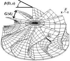 |
Fig. 1. Controlled parameters of the geometry of the "stencil" turbine TKR-7.5 TV: G (d) - "throat section" of the channel; (D, z) - the angle of the turbine blade at the output
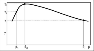
Fig. 2. The dependence efficiency (g) turbine wheel TKR-7.5 TV from the angle of the scapula (b) output channel: b1 - before optimization; b2 - after numerical optimization; b3 - when mak- ing the optimal design
To assess the possibility of changing the geometry of the inter-blade channel due to deformation of the blade profile during manufacture, it was made selective measure- ments of the" throat section " of the channels G of the turbine wheels (the smallest distance from the surface of the trough at the outlet at a given diameter of one blade to the surface of the back of the adjacent blade, Fig. 1).
For the turbine wheel TKR-7.5 TV measurement "throat section" on the peripheral diameter D2п (71 mm) five stencils gave a stable size of 8.8 mm with a maximum deviation of 0.2 mm (Table 1). The outer diameter of these stencils D1 = 79.1 mm with a nominal size on the mold D1 = 80 mm, D2п = 72 mm. if you insert the displacer into the stencil channel, the gap is about 1mm between the stencil and the form of the displacer. The planned size of the "throat section" (G) at d = 71 mm was 9.6 mm. Reducing the size of the "throat section" (G) to 7.1...8.8 mm corresponds to a de- crease in the angle of inclination of the guide profile b by d = 71 mm at 4.5° ± 1°.
Table 1. Measurements of "throat sections" G (d=71mm), mm blades five wax models turbine wheel TKR-7.5 TV
shoulder number
1 | 2 | 3 | 4 | 5 | 6 | 7 | 8 | 9 | 10 | 11 |
8.85 | 8.85 | 8.85 | 8.85 | 8.7 | 8.9 | 8.8 | 8.8 | 8.95 | 8.7 | 8.9 |
8.8 | 8.7 | 8.9 | 8.75 | 8.95 | 8.85 | 8.7 | 8.75 | 8.7 | 8.8 | 8.8 |
8.75 | 8.85 | 8.85 | 8.75 | 8.95 | 8.75 | 8.75 | 8.75 | 8.8 | 8.8 | 8.8 |
8.7 | 8.75 | 8.8 | 8.5 | 8.9 | 8.7 | 8.6 | 9.0 | 8.7 | 8.8 | 8.8 |
8.7 | 8.7 | 8.65 | 8.9 | 8.8 | 8.7 | 8.7 | 8.7 | 8.65 | 8.75 | 8.7 |
In the study of casting turbine wheel TKR-8.5 found the following. The plastic displacer did not reach the end of the casting channel by about 4 mm. (for different castings: 4.2, 4.5, 4.3, 3.9, 4.4, 4.6, 3.9 mm). It is noted that the penetration of the displacer into the channel (which must completely repeat the shape of the displacer) is prevented by premature contact of the surfaces at the turbine outlet, which character-
izes the decrease in the angle of inclination of the guide profile of the metal casting. A similar operation carried out for the stencil showed that the displacer goes deeper into the stencil (gap -0.7. 1.5 mm). Despite the fact that the stencil seems to be closer to
the planned geometry, it is in it that the main part of the final error is laid.
Control measurements of G on the nominal diameter D2п = 81 mm in 8 impellers of turbines TKR-8.5 TV, passed the working tests, showed instead of the nominal size of
10.6 mm average 10.0 mm with a deviation of 0.2 mm. One of the wheels had a change in the size of the "throat section" in the range from 9.0 to 11.0 mm, including
10.5 mm. It showed the worst performance. The other wheels had a lower efficiency of 1. 2 % due to errors in wheel geometry.
For the serial production technology of impellers, the analysis of technological stages was carried out for the appearance of the error of shaping (in particular, the size of the "throat section"). Thus, tasks were set:
· Statistical evaluation of errors introduced at each stage of manufacturing with the allocation of random and natural components;
· Research of the factors determining natural changes of the geometrical dimensions,
with the purpose of forecasting, stabilization, and total technological change in the preparation of source tables for CNC machines in the manufacture of the original masterform for displacers;
· Research on determinants of random scatter geometry for a technologically justi- fied to minimize it;
· Development of a rational system of control operations for the technological proc- ess of manufacturing wheels.
Step 1. Production of the master form (mold) for molding of the displacer by milling of three surfaces: a back, a trough and the closing surface of a trough on axisymmetric preparations on the CNC machine. Milling is carried out by successive passes along the cutter forming in the end plane of the wheel with a step along the length of the master.001 m. Then surface polished. The error of this stage is small and is mostly random.
Step 2. Production of a mold is made in two operations in the following order: dis- placers are cast, and then collected in a mold.
In the manufacture of plastic displacers is poured into the master form. The errors of this operations are associated with insufficient accuracy of positioning of the chan- nel displacer and its platform - a conical prism with an angle equal to 360/N. Manu- factured displacers after manual processing are assembled into a mold. This is one of the most important operations. It mates the surface of the trough on the molded dis- placers N times. Even with a gap between its of about 0.001 m (see Step 1), a 0.1ꞏN mm error is accumulated on the last displacer, which is eliminated by manual fitting. This operation (Step 2) is defined as the main source of random errors.
At the Step 3, wax models of the wheel (stencils) are made. The introduced errors are associated with the shrinkage of the wax model and the spatial deformation of the wax of the impellers due to uneven heat removal from the blades and the hub. The key is the low level of thermal conductivity of the wax model in comparison with the metal casting, technologically determined high cooling rate of the wax (within 5 min- utes by immersion in water), low modulus of elasticity of the wax.
This Step is estimated as the main source of systematic errors affecting the reduc- tion of linear dimensions and the occurrence of angular deformations (decrease in the angle of flow out of the wheel).
At the Step 4, the gating ceramic form of the turbine wheel is made by the method of multiple coating of the wax model (10-12 times) with a special suspension with its subsequent drying. Insertion error associated with the thermal expansion of ceramic forms by pouring of the melt.
During the last Step, the heat-resistant alloy is cast into a mold. The introduced er- rors at this stage can be considered insignificant and compensating errors of the pre- vious stage (due to the expansion of the ceramic form).
Due to the presence of sources of errors of systematic and random nature in the production of the task, first, to stabilize the errors that are natural (by maintaining the mode of casting stencils), calculate and take them into account in the preparation of data for control programs for CNC machines. Secondly, to minimize the errors of random nature, arising mainly at the stage of mold Assembly by increasing the accu- racy of the previous stages. Thirdly, without a certain level of production culture, which includes, in addition to high technological discipline, also the control of all components of quality, it is impossible to improve the quality of turbines as a whole. In this regard, it was proposed to make in the technological process of manufacturing castings of the wheels of the operation to control the value of "throat section" of the channel.
The attention to the stability of the blade thickness field was paid from the very be- ginning of the development of the technology of serial production of turbine impel- lers. In order to increase the stability of the blade thickness field, the technology of mold manufacturing was improved, in particular, the separate production of mold displacers by milling was replaced by casting into the master mold. Table 2 presents the results of statistical processing of thickness measurements T(i) at 13 points of 36 turbine blades TKR-11, obtained by successive grinding of the impeller - the average thickness M[T(i)] and the standard deviation s[T(i)]). The location of the points for which thickness measurements were carried out is shown on the cylindrical projection of the blade (Fig. 3). As can be seen from the table. 2 the average thickness at some points reaches 19 %.
Table 2. Statistical characteristics of thickness T (i), mm TKR-11
i node | z(i), mm | d(i), mm | M[T(i)] mm | s[T(i)] | (s/M) 100 % |
1 | 12.5 | 110 | 1.24 | 0.139 | 11 |
2 | 6 | 110 | 1.70 | 0.089 | 5.2 |
3 | 16.6 | 94 | 1.64 | 0.211 | 13 |
4 | 8 | 94 | 2.19 | 0.103 | 4.7 |
5 | 26 | 85 | 0.86 | 0.128 | 15 |
6 | 26 | 78 | 1.05 | 0.200 | 19 |
7 | 18 | 78 | 1.77 | 0.159 | 9 |
8 | 8 | 78 | 2.56 | 0.148 | 5.8 |
9 | 26 | 62 | 1.40 | 0.120 | 8.6 |
10 | 18 | 62 | 2.24 | 0.128 | 5.7 |
11 | 8 | 62 | 2.97 | 0.117 | 4.0 |
12 | 26 | 46 | 1.72 | 0.168 | 9.8 |
13 | 18 | 46 | 2.42 | 0.166 | 7.0 |
Due to the complexity of the manufacturing technology of molds for smelted mod- els, the level of heterogeneity at similar points of the blades was reduced. So, on con- trol measurements of products of JSC AVTRAMAT this value did not exceed 0.15 m×10-3 that corresponds to requirements of specifications.
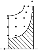
Fig. 3. Cylindrical projection TKR-11
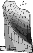
The characteristic distributions of the stress intensity si of turbine wheels before op- timization of the blade profile geometry according to the joint criteria of gas dynamics and strength are given on the Fig.4, a and after (Fig.4, b) in the field of centrifugal forces. Usually, after the optimization stage, the average stress level increases, and the
resulting project is more sensitive to the technological errors of geometry. The static strength margin of the optimized turbo wheels is about 2.0.
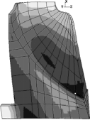
a b
Fig. 4. The characteristic shape of the intensity distribution of the stresses si wheels of turbines in the field of centrifugal forces: a-before optimization (TKR-11); b - after optimization by gas- dynamic characteristics (TKR-8.5 TV).
![]()
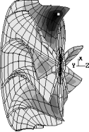
![]() For finding the ultimate and the statistical estimates of scatter s m turbine wheel used the theory of sensitivity analysis applied to the finite element model of the wheel on the basis of three-dimensional ISO-parametric 20-node finite elements (FE). On the Fig. 5 it is given the pattern of sensitivity analysis maximum stress intensity to the normal increments of the nodes of the grid FE ¶(s max)/¶( n ) for the turbine wheel TKR-8.5 TV.
For finding the ultimate and the statistical estimates of scatter s m turbine wheel used the theory of sensitivity analysis applied to the finite element model of the wheel on the basis of three-dimensional ISO-parametric 20-node finite elements (FE). On the Fig. 5 it is given the pattern of sensitivity analysis maximum stress intensity to the normal increments of the nodes of the grid FE ¶(s max)/¶( n ) for the turbine wheel TKR-8.5 TV.

Fig. 5. ¶(simax)/¶( n ) for turbine wheel TKR-8.5 TV
The picture of sensitivity analysis simax to the thickness of the turbine TKR-8.5, and the dispersion is acceptable and the actual thickness variation across the surface
![]()
![]() of the blades and hub is calculated standard deviation simax, equal to 1.6 % of s max ,
of the blades and hub is calculated standard deviation simax, equal to 1.6 % of s max ,
which indicates a relatively low effect of different thicknesses on the maximum stresses in the field of centrifugal forces. Qualitatively from Fig. 5 it can be seen that
![]()
![]()
![]() the area at the root of the blade at the outlet of the flow for the back and trough has a different sign sensitivity, that is, the greatest influence on the s max is the movement of the middle surface of the blade, and not the change in thickness. For the blade area along the outer meridional circumference opposite - s max grows with increasing thickness. The reduction in the thickness of the interscapular region of the disk leads to a decrease in s max.
the area at the root of the blade at the outlet of the flow for the back and trough has a different sign sensitivity, that is, the greatest influence on the s max is the movement of the middle surface of the blade, and not the change in thickness. For the blade area along the outer meridional circumference opposite - s max grows with increasing thickness. The reduction in the thickness of the interscapular region of the disk leads to a decrease in s max.
Taking into account the errors of the turbine wheel shaping practically does not change the magnitude and nature of the temperature effect from the exhaust gases in the cylinders.
![]() Real "variable thickness" of the blades also results in frequency detuning of the blades is cyclically symmetric structures (CSS) of the wheel. This affects the stratification of the earlier times the natural frequency (NF) oscillation of the blade crown, the earlier the harmonic distortion in the circumferential direction (for similar points) of their own forms (OF) of the oscillation, causes a redistribution of energy in forced oscilla- tions between the shoulder blades and, ultimately, leads to the spread of the resonance voltages, the increase of dynamic loads of the blade row in general. Given the known nature of the fatigue strength curve, a 50 % increase in dynamic stress (s max) can
Real "variable thickness" of the blades also results in frequency detuning of the blades is cyclically symmetric structures (CSS) of the wheel. This affects the stratification of the earlier times the natural frequency (NF) oscillation of the blade crown, the earlier the harmonic distortion in the circumferential direction (for similar points) of their own forms (OF) of the oscillation, causes a redistribution of energy in forced oscilla- tions between the shoulder blades and, ultimately, leads to the spread of the resonance voltages, the increase of dynamic loads of the blade row in general. Given the known nature of the fatigue strength curve, a 50 % increase in dynamic stress (s max) can
reduce the life of the product by 3 to 5 times.
Wheel continuity and high NF cause relatively low levels of damping, which in- creases the risk of resonant stresses. In addition, the structure of the midrange spec- trum is (Table. 3) that at the bottom is a package of "blade" oscillation frequencies generated by the first OF vibrations of the isolated blade. The relative density of this package is commensurate with the magnitude of the frequency disorder of the isolated blade, which characterizes the most dangerous, in the sense of the possibility of maximum overload, the region of the ratio of the parameters.
Two statements of a problem - extreme and statistical deserve attention. The first can be formulated as follows: "As far as possible to increase the resonant voltage (this value is called "overload" b) in the worst location of the different frequency of the blades, and feasible if the values for characteristic errors of morphogenesis serial manufacturing technology? Regardless of the nature of the relationship of the blades as subsystems of the CSS (elastic, inertial, aeroelastic, etc.) calculated maximum overload value (maxb) 11-blade wheel for resonance at multiples of earlier NF maxb m = 1.67 (for non-multiple NF - maxb nm = 2.16).
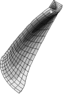
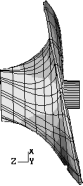
Based on the specifics of the spectrum of OF wheels (bottom package OF wheels from the first OF of the scapula, areas of high sensitivity fluctuations of the package located on the blades - Fig. 6, the density factor of the OF packet is more important than the exact frequency matching) next, a discrete model of the blade crown was used, (Fig. 7) with an elastic coupling of subsystems corresponding to the wheels of turbines TKR-8.5 TV in value and width of the "blade" midrange package. In this paper, for such a model, the feasibility assessment is carried out (Table. 4)worst fre-
quency detuning. As shown below, all frequency detuning values are in the range of possible frequency deviations of the serial technology used.
Table 3. Eigenfrequencies wi of blades, disk and turbocharger TKR-8.5 TV, Hz
Insulated impeller blade | Wheel hub (without blades) | |||||
i | 1 | 2 | 3 | 1 | 2 | 3 |
wi | 7242 | 15032 | 19292 | 9950* | 1005 | 10875* |
No. | The blade wheel of the turbine (blade package OF), * - multiple frequencies | |||||
i | 1, 2 | 3, 4 | 5, 6 | 7, 8 | 9, 10 | 11 |
pi | 6075* | 6126* | 6135* | 6140* | 6145* | 6365 |
m | 1 | 2 | 3 | 4 | 5 | 0 |
Disk OF | Blade package of SF on the basis of the 2nd SF of the scap- ula | |||||||
i | 12 | 13, 14 | 15, 16 | 17, 18 | 19, 20 | 21, 22 | 23, 24 | 25 |
pi | 10490 | 10690 | 12000 | 12190 | 12285 | 12333 | 12355 | 12990 |
m | 0 | 1 | 2 | 3 | 4 | 5 | 6 | 0 |
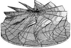
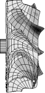
Fig. 6. The sensitivity analysis of common-mode NF ¶(p13)/¶( n ) of the blade NF package (turbine TKR-8.5 TV)
The frequency separation of the blades for the entire wheel casting technology is random and does not allow selective Assembly (unlike axial turbomachines). In the statistical formulation of the problem on the statistical characteristics of the deviations of the geometry (or different frequencies) of the blades (usually the normal distribu- tion hypothesis is used), the density of the probability of overload at resonant oscilla- tions is investigated. To answer the question whether the increase in the accuracy of
wheel shaping (for example, due to the development of new technologies) will lead to a decrease in the overload in the statistical formulation, it is necessary to build a de- pendence of the stochastic characteristics of the overload on the initial characteristics (dispersion of the different frequencies of the blades).
![]()
![]() Table 4. The worst (even) detune PRi =(Dp 2 / p 2 ) /R2, causing maximum overload bmax at
Table 4. The worst (even) detune PRi =(Dp 2 / p 2 ) /R2, causing maximum overload bmax at
resonance k-th harmonic excitation (pnom = 7.5 KHz, viscous friction n = 0.1, R2 = 0.01, N = 11)
PRi ( i- shoulder number) | b | ||||||
K | i =1 | i =2, 11 | i =3, 10 | i =4, 9 | i =5, 8 | i =6, 7 | |
k=0 | -1,042 | 3,7994 | 0,5781 | 0,3419 | 0,6591 | 0,4330 | 2,1573 |
k=1 | -,3683 | 3,6298 | 0,7651 | 0,6905 | 0,8534 | 0,8005 | 1,6725 |
k=2 | -,0217 | 5,9146 | 0,5371 | 0,5371 | 0,6255 | 0,5366 | 1,6723 |
k=3 | -,0551 | -12,363 | -0,2113 | -0,2464 | -0,1550 | -0,2646 | 1,6715 |
k=4 | -,0018 | -3,8313 | 0,2001 | -0,9743 | -0,8505 | -0,7502 | 1,6699 |
k=5 | 1,7835 | -2,0662 | 0,4598 | 0,4121 | 0,5366 | -0,3232 | 1,6689 |
Experimentally (using a frequency analyzer of the firm "Bruel and Kjaer" for iso- lated blades) found that the magnitude scatter of the fundamental tone of real blades (6700 Hz) is found for the investigated wheels turbine TKR-8.5 TV in the range up to 300-500 Hz c dispersion s[Dpi] @ 100 Hz. We will use the "detuning parameter" (PR) [15-16], defined for the wheel as the ratio of the square of the maximum relative frequency detuning of the blade to the density of the simulated eigenfrequency pack- age ("generated" by the first eigenform of the isolated blade oscillations):
PR = max{( p2 - p2
) / p2
} / R2
(1)
i =1, N
i nom nom
where R2=[(fN-f1)/f1]/4 is a quarter of the relative width of the eigenvalue package (approximately the square of half the relative width of the NF package), determined in the model by the value of weak elastic bonds. From table. 3 it can be seen that the blade package R2 @ 2.44 % of 2.44 %. Thus, the applied serial technology is charac- terized by the level of the detuning parameter s[PR] @ 1.2 (PRmax @ 5).
The "analytical solution" of the problem in the statistical formulation within the framework of linear relations of the sensitivity analysis overload to the frequency disorder of the blades and the application of statistical theorems on linear operations over normally distributed random variables (methods of statistical dynamics) is lim- ited by the scope of applicability of the first approximations of the classical (system with strong coupling) or modified (system with very weak coupling) perturbation methods. However, for the studied levels of parameter mismatch (PR @ 0,5–5) is characterized by essentially nonlinear dependence of the system loading on the mag- nitude of the frequency detuning of blades. This does not allow the use of linear (or quadratic) relations in the description of the dynamic characteristics of the upset sys- tems. Therefore, to find the probabilistic characteristics of the overload is justified by the use of methods of mathematical statistics, where as a sample of observations of a random variable is a set of overloads of the system, calculated by numerical genera-
tion within the normal distribution law. In this paper, the method of numerical ex- periment was used for the discrete model of Fig. 8. Different frequency of blades was considered to be non-randomized and distributed according to the normal law with the dispersion s(PRi).
w1blade = 7242 Hz w hubs = 9950 Hz p5,6 = 6135 Hz p15,16 = 12000 Hz
![]() Fig. 7. The natural frequencies and mode shapes of the turbine TKR-8.5 TV
Fig. 7. The natural frequencies and mode shapes of the turbine TKR-8.5 TV
As the random misalignment with a standard subroutine for generating random
numbers with a constant law of distribution in the open area ] 0,1 [ with the initiali-
zation at the current time, which according to the known dependences were converted to normal distribution of the different incidence of the blade with the given mathe- matical expectation (ME) and standard deviation (SD, s). The sample of a random variable of different frequencies for each individual blade was previously checked for compliance with the normal distribution law according to the criterion c2 by the sig- nificance level a = 75 %. Then the problem of forced oscillations was solved for 1000 types of frustrated crowns obtained in this way, statistical characteristics b[s(œfi)] or
b[s(PR)] were calculated. The dependence of МE{b[s(PR)]} was constructed simi- larly by 25 values of s*(œfi) for a given excitation harmonic (Fig. 8).
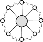
Fig. 8. The discrete model of a quasi-periodic structure consisting of a set of elastically coupled subsystems
According to this method, the 11-blade turbine wheel TKR-8.5 TV (N = 11) was studied. For Fig. 9 shows the dependence of ME overload (МE{b[s(PR)]}) from the value of SD "parameter mismatch" (s[PR]) at resonance with the 5 (6) harmonic excitation, and the interval ME(b)+s(b)left, ME(b)+3ꞏs(b)left, ME(b)+s(b)right, ME(b)+3ꞏs(b)right, the limit of rating overload bmax = 1.67, bmin = 1.0. For
s[PR]serial.@ 1.2 at resonance on the excitation harmonic k = 5 or k = 6: ME(b)=1.44,
s(b) = 0.1, the coefficient of asymmetry – 0.85, coefficient of kurtosis 0.4.
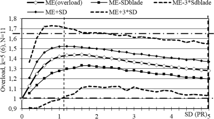
Fig. 9. Dependence of ME overload of МE{b[s (PR)]} on the value of the SD of the "detuning parameter" at resonance with 5 (6) excitation harmonic, N = 11. Dotted vertical line -
SD(PR) = 1.2 a serial manufacturing technology turbowheels, dashed "bold" - max level (PRmax @ 5), the dot-dash horizontal limit of rating overload (bmax = 1.67)
It is obvious that the accuracy of the real optimal resource design of the structure should correspond to the accuracy of its manufacture. Casting technology of manufac- turing turbine wheels and compressors, having undoubted advantages (low cost and high performance), requires consideration and modeling of the errors of forming a natural character at the stage of formation (phase transition and cooling) wax model (stencil). In comparison with steel casting, the wax has more significant temperature gradients after the phase transition (due to the significantly lower thermal conductiv- ity of the wax mixture compared to steel) and is much more prone to deformation when thermal stresses occur due to the lower (compared to steel) modulus of elastic- ity. With a certain degree of error, it is possible to analyze the movements of the sten- cil by determining the temperature field after the phase transition (assuming at this point in time the wax shape of the wheel is perfectly accurate and unstrained) and
solving the thermoelastic cooling problem. This solution will also allow to establish zones of possible residual stresses.
To stabilize and reduce these effects, it is necessary to improve the technological mode of the phase transition of the stencil (fixing and increasing the time), improve the wax composition (increasing the modulus of elasticity), pre-registration of the deformation of the stencil in the manufacture of the mold of the displacer or the de- velopment of technology that uses not wax models, but, for example, Quick-Cast and 3D-Prototyping technologies.
It is shown that the most dangerous consequence of technological deviations of the casting geometry of turbine impellers is the possibility of growth of resonant dynamic stresses. For serial manufacturing technology, estimates (for a discrete system with the corresponding partial frequency of the subsystem and the spectrum density) of the maximum realized overload (maxb kr =1.67) and statistical characteristics of the over- load (ME(b) = 1.3, s (b) = 0.125). The conclusion is made about the rationality of further reduction of different thicknesses in order to reduce possible overloads at resonant oscillations (M serial.(b) are positioned relative to M max (b) [s(œfi)]) due to improvement of technology of manufacture of castings turbochargers’ wheels.
Thus, computer simulation showed that there is a significant change in the geome- try of the turbine blade, which adversely affected the geometry of the resulting cast- ing. Was proposed and solved by the method of computer simulation of "reverse" task of the task of such a geometry of the mold, the solidification of the stencil in water and its deformation led to a (given) geometry of the resulting casting of the turbine of the turbocharger. The solution of this problem by the method of computer modeling allowed to reduce the production defect on the discrepancy of the turbine blade ge- ometry of the turbocharger by 90 %.
Contact:Mr Liu
Mobile:15869109368
Tel:86-571-89967020
E-mail:info@dawopu.com
Address:No151 ,ZiDingXiang Rd, Hangzhou. Zhejiang Province, China